Pin Map and Connections
Pin Map and Connections
The pin map and connections of your XFly Drone play a vital role in integrating additional hardware and customizing its functionality. This guide offers a detailed overview of the available pins, including I2C, SPI, UART, and power connections. Whether you’re a beginner or an experienced user, understanding these connections will allow you to expand your drone’s capabilities safely and effectively.
Understanding Pin Configurations
Before working with the pin map, it’s important to familiarize yourself with the layout of the XFly Drone’s pin headers. These pins are grouped logically to support key hardware components and ensure efficient communication. Misusing or improperly connecting these pins could lead to malfunctions or damage, so it’s crucial to follow this guide closely.

Pin Configurations
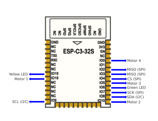
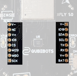
- I2C lines are shared by the BMI270 IMU and the ToF sensor. For further connections, I2C pins are included in the top pin header rows.
- SPI port is used by the PMW3901 sensor. These pins are included in top pin header rows for additional hardware.
- TX and RX lines are used by the UART chip for programming and Serial Monitoring. If using for any other purposes, make sure to disconnect or disable the new function when uploading the code.
External pin headers

BAT Pin:
- The BAT pin delivers direct battery voltage, which ranges from 3.3V to 4.2V, depending on the battery’s charge status. You can use it to monitor battery levels.
V+ Pins:
- There are two regulated 3.3V output pins available for powering additional hardware.
V- Pin:
- The V- pin provides a reliable ground connection (GND) for all connected devices.
Pin Configurations
I2C Connections
The I2C lines handle communication for the BMI270 IMU and the ToF sensor, both of which are essential for flight stabilization and obstacle detection. Additionally, you can use the extra I2C pins located in the top pin header rows to connect more devices. These pins allow you to integrate external sensors, such as barometers or magnetometers, which can significantly expand the drone’s functionality.
Pro Tip: When adding multiple devices to the I2C bus, ensure each device has a unique address to avoid communication conflicts. Otherwise, the devices may not work correctly, leading to operational issues.
SPI Port
The SPI port is used by the PMW3901 sensor, which is responsible for motion tracking. If you need to integrate additional SPI-compatible devices, such as external memory modules or advanced sensors, you can rely on the SPI pins available in the top pin header rows. This flexibility makes the SPI port a powerful option for expanding your drone’s capabilities.
Did You Know? The SPI interface supports faster data transfer rates compared to I2C, which makes it ideal for high-performance peripherals. However, you should always ensure that the connected device operates within the XFly Drone’s power and voltage specifications. Otherwise, it could lead to device malfunctions or damage.
UART (TX and RX) Lines
The TX and RX lines primarily support the UART chip for programming and serial monitoring. This setup allows you to upload firmware and debug the drone’s performance. However, if you plan to use these lines for other purposes—such as connecting GPS modules or external communication devices—you must disconnect the UART functionality first. This ensures that there are no conflicts during code uploads.
Safety Note: Avoid using the UART pins simultaneously for programming and external functions. Otherwise, you may encounter unexpected behavior or errors, which can compromise the drone’s performance.

QubeBots Pvt Ltd is a startup that focuses on developing Edutech products to support the global STEM Education system.
Contact us
hello@qubebots.com
+94 77 069 5151
Colombo, Sri Lanka